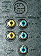
Hello, I have an Acoustimass 9 that I want to connect to a Pioneer 5.1 amplifier. Is it possible? can you help me in building an adapter to the bose din? (attached picture).
Lorenzo, I have just got a schematic for the amp. I am trying to utilise it for a sub. Are you looking at just using it for a sub, or what are your intentions. There is a couple of issues that I can see to start. ie the amp is turned on my an external voltage (from controller) looking at bypassing that at the mo. Second issue is volume controll of the amp which comes from serial data, however this is also bypassable with some effort. I will let you know how my project progresses
The prior owner had a really crappy repair-job on the input-cable (the 8-pin DIN-cable). I cant understand how he have connected this? It seems that:
top of 3,5mm is connected to pin 7 mid of the 3,5mm is connected to pin 3 base of the 3.5mm is connected to pin 6
ground on the rca:s is pin 5 and pin 2 Tip of rca:s is pin 4 and pin 1
Is this correct? (pinouts according to the "maleside" of this: http://freespace.virgin.net/tom.baldwin/DIN8-pinout.gif )
Feels that I have to start with checking all the cables before I start digging into the sub
With best regards Olof
Mark BurgessBronze Member Username: Mr3dzpop
Woodstock, Georgia USA
Post Number: 57 Registered: May-07 Posted on Sunday, March 02, 2008 - 08:09 pm:
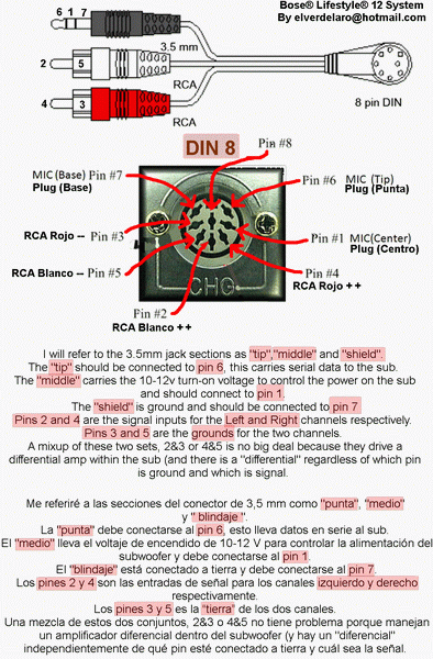
-------------------------------------------------------------------------------- Olof, I will refer to the 3.5mm jack sections as "tip","middle" and "shield". The "tip" should be connected to pin 6, this carries serial data to the sub. The "middle" carries the 10-12v turn-on voltage to control the power on the sub and should connect to pin 1. The "shield" is ground and should be connected to pin 7
Pins 2 and 4 are the signal inputs for the Left and Right channels respectively. Pins 3 and 5 are the grounds for the two channels. A mixup of these two sets, 2&3 or 4&5 is no big deal because they drive a differential amp within the sub (and there is a "differential" regardless of which pin is ground and which is signal. The important ones are of course the ones for serial Data and turn-on voltage. Make sure they are correct. And by the way, the reference you found for the male 8-pin DIN connector is correct.
Sorry for pasting someone elses thread on here but it may help.
Hi, I have a bose acoustimass 9 sub too. May I know what is a "serial data" as you have describe and how can I generate it?
By the way, the male jack is it the one which is connect to the cable? and the female jack is located at the bottom of the sub? Please correct me if I am wrong. Thank you....
Regarding the Acoustimass 9 Sub, I was wondering whether it would be possible to utilize this for public performance, that is, in being connected to a Roland (Acoustic Chorus) AC-60 amplifier, especially since the Roland does have a 1/4" plug outlet for connection to a powered subwoofer.
Hi All, I need to connect my Bose Lifestyle 20 powered sub to CD player. Would you kindly to guide me the wires should be connected from my CDplayer to this sub model? It has 5 pins female connector on this sub. I will do it myself to make this cable link if anyone would help me out for this matter.
i have an am9 sub and i want to connect it to avr, however i know i need to send a serial command to turn it on and another to turn up the volume. short of making up a pic MPC to do this. does anyone know of any other way to get this sub powered up. i have seen in the forum that theres a way to put it in to test mode that will give me the sub functionality that i need.