How to DIY Repair a Bose Lifestyle 12 subwoofer
| Thread | Last Poster | Posts | Last Post | |
|---|---|---|---|---|
| Archive through September 12, 2009 | Rahul | 100 | ||
| Archive through April 10, 2009 | Owen Deckinga | 100 | ||
| Archive through January 19, 2009 | Mark Sanders | 100 | ||
| Archive through July 06, 2008 | Sridhar Srimushnam | 100 | ||
| Archive through March 15, 2008 | Ricardo Lozano Garza | 100 | ||
| Archive through January 06, 2008 | Mark Burgess | 100 | ||
| Archive through December 25, 2006 | Joseph Coulson | 98 |
|
New member Username: JeffgoddPortland, OR Post Number: 2 Registered: Sep-09 | Rahul, I think you've got it. It is the 2683 and there is dark brown goop all over the place. When I get home I will measure how conductive the goo has become. It is pretty darn dark brown. I guess I should begin to get scared... Thanks for getting me started! Jeff |
|
New member Username: JeffgoddPortland, OR Post Number: 3 Registered: Sep-09 | Rahul, It is true, I have conductive brown goo... |
|
New member Username: MongkolPost Number: 2 Registered: Sep-09 | Hi Mark, I am using Bose Life Style 20. The CD magazine is stuck and making noise. Could you please send me the instruction on how to fix this problem? My email: mongkol@motorola.com Appreciate your help. Mongkol. |
|
New member Username: Sammy09HAWAII USA Post Number: 3 Registered: Aug-09 | I have AM25P II sub I would like to upgrade my CD5v2 console to AV28. So, my question is. My AM25PII still be compatible to AV28 console? Any suggestion or help I really appreciate. Sam |
|
Silver Member Username: Mr3dzpopWoodstock, Georgia USA Post Number: 213 Registered: May-07 | Sam, You can use the AV28 with your AM25PII. Use the BoseLInk output to connect it to your sub. All the particulars of set up and control are in the owner's manual for the AV28. Good luck. Mongkol, I have sent the info you need to your email address. Good Luck. Rahul, Thank you for taking care of Geoff, you handled that extremely well. I am having a hard time being on here of late as I am in the midst of a big project and all my computer time is being taken up. As soon as I can get this finished I will be back as usual. Thanks for your patience. Mark B. |
|
New member Username: Sammy09HAWAII USA Post Number: 4 Registered: Aug-09 | Thanks Mark for your reply. Sam |
|
New member Username: Bill60750SantiagoChile Post Number: 3 Registered: Aug-09 | Hi master Mark : i have read many posts but can't find solutions for me : 1-Can connect lifestyle 30 home theater speakers to lifestyle 5 music center ? (diagram pin ) 2- Can you send me the diagram pins for connect the lifestyle 30 home theater with lifestyle 20 3- I have another lifestyle 5 with the display with poor bright,do you have instructions for repear it(change capacitors) From Chile ,so far,Bill , email plarenas@dei.cl |
|
New member Username: Sammy09HAWAII USA Post Number: 5 Registered: Aug-09 | Patricio, If your lifestyle 30 SUB comes with 13PIN, yes you can connect it to CD5 console. You can go back to achive through july 6, 2008 all the way down you can see the diagram there for 13 PIN. If you have CD5V console you can change C19 for the display. If you have CD5V2 console you can change cap C12,C15,C16,100uf@25v & C17 33uf@63v for the display. I hope that will help your problem. Sam |
|
New member Username: AhinesDORAVILLE, GA Post Number: 3 Registered: Sep-09 | Hi Mark I am so glad to have found this site and ask questions to someone that can answer and not guess the answers. I am trying to hook up my bose sub am25 to my yamaha reciver and I've been reading some of the past post and and I have the same problem red and white rca's ,sub wire and 3.5 mm plug. can I get you to email me a copy of the schematics, the layouts and the the service manual to show me what I need to do and also can I use all the speakers with the system after I rewire it to work on the reciver and what can I use for the ground and and 10 volt power souce to turn on the sub. antonioandrose2000@yahoo.com |
|
New member Username: AhinesDORAVILLE, GA Post Number: 4 Registered: Sep-09 | HI Mark Thanks for getting back to me it is the series 2 |
|
New member Username: Aaron393New York, NY USA Post Number: 1 Registered: Sep-09 | Hi Mark, I'm really glad that I came across your forum because I've been scratching my head trying to figure out what's happening with my Bose system. Here's the problem, i'm sorry if you've answered this previously but i will continue to look through the older posts to see if this was asked before, I've recently moved and now that i'm trying to connect my Bose Lifestyle 5 and I cant get anything from the speakers. Now I've gone through all the pre-checks that I can think of and still nothing. Everything from the media center works because I've checked that with a headphone and I get sound from all the sources but nothing comes through the acoustimass or the speakers connected to it. I don't even get any indication that the acoustimass is powering up because there is no sound when its powered up; there should be a thump at least. Is there a fuse that could have been blown or something of that nature in the acoustimass that I can change or do you suggest that i return it to Bose to have it serviced? |
|
Silver Member Username: Mr3dzpopWoodstock, Georgia USA Post Number: 214 Registered: May-07 | Aaron, First of all please understand this is not MY forum. I am only a contributor and do what I can to help others. As far as your problem is concerned this first step is to disconnect the cable from the subwoofer and try powering it up by itself. Just plug it in and if the sub is OK it will come on. (thump) If not then you will have to get inside to check things out. Yes there is a fuse that may be open but then there is quite a bit more going on. Check for continuity between the red and black wires going to the transformer. It should check a relatively low impedance. Beyond this check I'll have to wait till you have the prints and service manual. They have been sent to your email address. |
|
New member Username: ChemanPost Number: 1 Registered: Sep-09 | HI Mark Can you send me the schematic diagram for the bose lifestyle 12 head unit console and Subwoofer unit. mcharkree@yahoo.com I grately appriciate in advanced for you help. Che man |
|
New member Username: Anupam1Post Number: 1 Registered: Oct-09 | Hi Mark, I plugged my 100 v Bose companion 3 Series II speaker set to 220v supply and it went dead. I opened it up and fixed the fuse. I can see that LED on control pod turns green after switching it on. But there is no sound out of speakers. When I connect headphone to control pod I can hear sound properly. When I switch off power supply, it plays the sound for ~2-3 seconds ( as if the caps are discharging). Could you please let me know what can be wrong. If you have schematic diagram of circuit could you pass it me at anupamtri@yahoo.com |
|
New member Username: Sammy09HAWAII USA Post Number: 6 Registered: Aug-09 | I have Bose 321 Serries II subwoofer. I would like to used it for my Pioneer receiver as my subwoofer but I don't have a diagram how to wire it. So please, anybody can send me the diagram how to wire it. Any help I really appreciate it. Sam |
|
New member Username: Yvonne69Post Number: 1 Registered: Oct-09 | Mark, Was there a fix for Mike Cooper's "volume goes all the way up to maximum and we can't turn it down" problem. I have the same unit and am experiencing the same problem.} |
|
New member Username: Simonjw5101Post Number: 1 Registered: Oct-09 | I have much the same problem that Aaron393 posted on Sep-09. I have a Lifestyle 28 Series 2 and no longer get any sound from the speakers. I just tried with headphones and all is OK. I opened up the Acoustimass and the only fuse I can see is fine. It really "feels" like it isn't getting any power...should there be any obvious sign that power is on (any lights, any noise, anything?). Cheers, John |
|
New member Username: MvnPost Number: 1 Registered: Oct-09 | Hi Mark, I need your help, I like to know how to turn on the AM800P, is that right I just need to apply +10V to pin 7? Do I need to apply +12V to pin 13? Could you please send me a diagram, my email address: dtbquyen@yahoo.com Thanks in advance for your help, Minh |
|
New member Username: SengusPost Number: 2 Registered: Sep-09 | Hi, I have a bose lifestyle 12 series, planning to replace it with a onkyor 876 receiver. I could connect cube speakers directly, but i dont know how to connect the bose Acoustimass to the reciever. Any help would be much appreciated. If anyone has schematic diagram of the acoustimass please send it to sengus@gmail.com |
|
New member Username: ToshanePost Number: 1 Registered: Nov-09 | Hi Mark, I have a similar situation to Steve's. We moved our Bose Life style 12 system to hook up a plasma TV. After I re-connected the system, only left and right speaks have sound no. There is no sound from sub woofer and center and rear speakers. Could you please let me know what I should do? thank you very much. |
|
New member Username: Mason_leePost Number: 1 Registered: Nov-09 | Hi~ Mark. I have Lifestyle 25 Series II subwoofer and Bose lifestyle 20 Music center. I would like to upgrade my lifestyle 20 Music center console to AV38 Media Center. My lifestyle 20 Music center still be compatible to AV38 console? If it is possible, What kind of cable do i need... Please help~ I really appreciate. |
|
New member Username: Bahamaboy_242Post Number: 1 Registered: Nov-09 | Hi Guys! I Have a Bose Lifestyle 28 system and i have no power light on my acoustic mass module and no sound. I have opened it up and tested the fuse and switch. Both Passed. can you please help me someone. Thanks |
|
New member Username: JlswanyDallas, TX USA Post Number: 2 Registered: Nov-09 | I have a Bose LS-28 that the DVD sticks in the unit. opened it and found a broken belt in a toshiba DVD player. Can this DVD player be replaced with another IDE DVD player? John |
|
New member Username: MarcovaspOrlando, FL USA Post Number: 1 Registered: Nov-09 | I have a LIFE STYLE 12 II, seems like that my transformer is burn, check voltage alone on transformer and no energy out, my question, should I replace the transformer or should I send the sub woofer and console to Bose to repair?? Do they apply the flat fee to repair in this case??? Thank you, Marco |
|
New member Username: Sammy09HAWAII USA Post Number: 7 Registered: Aug-09 | Hi to everybody, Anybody have on idea what's wrong on my bose 3-2-1 serries I subwoofer. Are heard humming into my 321 subwoofer but my two speaker are fine it's just the subwoofer it does not produce bass. Any input greatly appreciated. Sam |
|
New member Username: JohondoRockwall, Texas USA Post Number: 1 Registered: Nov-09 | Great forum here. Thanks all for the wealth of valuable information. I have a Bose Lifestyle 5 Music System with the Acoustimass 9 Speaker system. It has the often mentioned problem of the Subwoofer bass channel not powering up. I do get sound from the 5 small satellite speakers, and I do have volume control, although it seems the channels are not amplified. All functions on the Music center unit do work. I do not get the bump indicating the unit is powering up. I have removed the cover from the subwoofer AM9P unit and found the fuse on the upper circuit board to be good. I have also confirmed that the 10.5 volt signal from the Model 5 music center is getting to the subwoofer circuit board through control cable (DIN Cable) connected to the "System Control 1" jack on the Model 5 music center. I have also confirmed the circuit board in the sub is getting 115 volts and that the main transformer has continuity through the red and black leads. I have noted previous threads that talk about the specific location of a failed100 ohm resistor (or other resistors) on the circuit board in the sub that will prevent a thyristor or triac from powering up the amplifier(s). However those discussions were specific the AM15 subwoofer module. Does anyone have the know if this problem/fix applies to the the AM9P module? If so what is the location and value of the resistor that may be in question? Does any one have the schematic diagram and the component layout for the circuits in the AM9P module? If the resistor fix does not apply to the AM9P module, does anyone know of any other commonly found problem that would prevent the base channel from coming on? I apologize if the solution to this has already been posted. I have spent about 3-4 hours researching the archives and have not been able to find information specific the AM9P, so I attempted the post. The subwoofer module model is AM9PODU223868 C9650 and the part number on the top circuit board is 175560-A (12-5-96) The Lifestyle 5 Music center is serial #306290 (Nov 1996) |
|
New member Username: Bluebird1955Birmingham, WestMidlands England Post Number: 1 Registered: Nov-09 | Hi, I have obtained a Lifestyle 20 6 cd system and would like to replace my Lifestyle 12 single cd with it. Is it possible? I cannot work out what the System Control jack will do on the 20? Any help? |
|
New member Username: Barrow1944Post Number: 1 Registered: Nov-09 | Hi I have a Bose lifestyle 18 series II which has a damaged main unit. Is it possible to hook up the five speakers and powered sub to a pioneer reciever. The connector to the head unit is a RJ45 at the sub end and a mini 8 pin din on the other. If someone could help me with the connection information please Thanks Jim |
|
New member Username: Just_n8Portland, OR USA Post Number: 2 Registered: Jul-08 | Mark - We have a Lifestyle system (pre-number era!) which is fairly similar to the Lifestyle 5 from what I can tell. It's connected to a Bose inVisible home system that was built into our house. The issue we've been having is that the sound will cut off intermittently - almost as if it gets tired (or hot). Usually turning it off for a few hours/days will resolve the issue, but today I found that if I switch inputs and turn up the volume, sometimes it will click back on and I can switch back to the original signal (e.g listening to radio, cuts out, switch to a CD and then switch back to radio when it comes on). Any thoughts on what it might be? I contacted Bose and they had no ideas other than "send it in, and we'll see..." for a couple hundred bucks. In the meantime, its driving me crazy! Thanks in advance for any directions/solutions. Cheers - Nate |
|
New member Username: MarkdrPost Number: 1 Registered: Dec-09 | To mark Burgess: Last week I was given a Bose Lifestyle Model 5 with a Bose powered Acoustimass 3ii set. The music center worked fine, except for the display. Thanks to Mark Burgess I knew I had to exchange capacitor # C19, so now it the display lights up! I appreciate your help, Mark! Perhaps Mark or another expert can help me with yet another minor problem concerning the woofer amp. When I power up the amp, first I get 3 seconds of silence, then 5 seconds of a hissing, slightly crackling sound, then the music comes on and it sounds terrific! After the set has been turned off, I can start it back up within 2 hours without the hissing start up sound returns. After about 4 hours, when starting up, the hissing/crackling returns. I think it has got something to do with the 2 giant 10.000 uF capacitors that may be leaking a bit, but I'm far from sure. Any clue to this problem is very welcome. I take it the first seconds of silence is normal. What exactly does the cable with jack plugs do. I read somewhere that it sends a 12v signal to the amp, but then what? Does it wake up the amp from hibernation? Does the amp hibarnate, or switch off completely? When the cable is unhooked from the woofer after it has started, the woofer continues to work, but when the jack plug is removed from the music center, all music stops. Why? |
|
New member Username: BigvivPost Number: 1 Registered: Dec-09 | hi! i noticed that someone sent through repair instructions for the lifestyle cd magazine style of bose. my issue is that the magazine is stuck and whirrs occassionally even if the system is off (but still plugged in). i opened it up to try and resolve as per others' experience here but with no luck, so maybe if anyone has step by steps, then please let me know! bigviv (at) gmail.com thanks!! |
|
New member Username: BigvivPost Number: 2 Registered: Dec-09 | whoops, double post! |
|
New member Username: RfiferPost Number: 1 Registered: Dec-09 | I have an LS28 that just stopped producing sound. My amateur assessment is that the Acoustimass unit is not getting power as described by others on this forum. Mark (if you are still out there) - I live in nearby Suwanee and would be interested in paying you to repair it. If you are interested, please e-mail me at rfifer1@bellsouth.net. |
|
New member Username: JackcuaPost Number: 1 Registered: Dec-09 | Mark, Thanks for sharing your experience and knowhow with all of us. You are great! I've a Boss Lifestyle 20 system. The CD Magazine was stuck and the Display was not working. Would apprecite it if you would email me the procedures to open the system and solve these 2 problems. My email address is "jackcua@hotmail.com". Thanks in advance! |
|
New member Username: Tw4motLawrenceville, GA USA Post Number: 1 Registered: Dec-09 | Hi Mark, You sound like the go to guy for all things Lifestyle. Great site. I have a LS 20 that is about 18 yrs old. It has the dim display issue, stuck/noisy CD feed, poor remote operating range and often drops audio when I FF my DirecTV receiver which is connected via SPDIF. I have to turn the LS-20 off/on to correct the audio issue. This system was originaly a LS-12 as I recall and I upgraded it to the 20 when the CD changer was made available and then add the new subwoofer when the unit supported Dolby. I recently purchased a Audio Authority C-1024a to use with the LS-20 and Harmony 880 remote. I've loaded the codes from the Logitech software tool but still can't get the Bose to respond to commands from the Harmony. The C-1024a is acknowledging commands via LED but no LS-20 response. So I have the following questions; 1) Could you forward the display fix? 2) Could you forward the CD fix? 3) Any ideas on the poor remote range? 4) Any ideas on the dropped SPDIF audio? 5) Any ideas on the lack of C-1024a functionallity? Thanks very much in advance |
|
New member Username: KilogsPost Number: 1 Registered: Jan-09 | Hi Mark, I have been looking through this forum for some time now lookiing for my answer and finally found that you emailed a pdf file to help someone with a similar problem. I have an old Bose lifestyle 25 system purchased back in 96'. What happens is the speakers make a loud pop and all audio stops. I then unplug and replug and most times it comes back on for a while and some times wont come back on at all. Thank you for your help in advance. |
|
New member Username: KilogsPost Number: 2 Registered: Jan-09 | Also if there is anybody reading these posts whom has recieved the troubleshooting instructions previously and could forward them it would be greatly appreciated. The unit is an old 96' lifestyle 25. My problem is the system makes a loud popping noise and cutting out audio. You then have to unplug and replug the power or power cycle the unit to get it to work again. Thanks Alot!! kahlilassad@hotmail.com |
|
New member Username: Barberr4aolcomPortsmouthUnited Kingdom Post Number: 1 Registered: Jan-10 | Hello Guys, please help with my problem, i have just reset up my Bose Lifestyle 12 series 11 system and now there is no sound, i have set up as per the hand book, the system works fine through head phones but not through the Acoustimass, not even a sound when i turn it on. (no on button anyway) i have checked all power cables etc. being a real novice at this sought of thing as this was set up for me in the first place, will the system still work as a cd player if the digital source cable is not plugged in.. (bet your thinking stupid question) please help anyone Rob |
|
New member Username: MiguelninoPost Number: 1 Registered: Jan-10 | Hi, I bought a Sony Home Teathre in USA, but the power of this is 120 AC, 60 Hz with 200 w. But in my country we have power 220 AC, 50 Hz. So please hel me. I have a question is possible the Home teathre acces in my country??? I must buy a voltage converter??? and additionaly buy a frecuency converter too ( From 60 Hz, to 50 Hz). Please help me soon. My best regards |
|
New member Username: G_daskiPost Number: 2 Registered: Jan-10 | I am new to all of this. I have had my Bose LS 12 since 1998 so I am assuming it is a series 1. I tried to use it for the 1st time in several months the other day and I have no sound. I have checked all of my cables and such and all seem fine. I notice when i turn up the volume that there is no volume display. All of the other displays show such as AM-FM and the station, CD track, etc. I tried playing a CD and using the radio and still no sound. I just plugged in headphones and I do have sound through head phones. Could this be as simple as a fuse somewhere? Any ideas or thoughts would be greatly appreciated. PLEASE make it very clear and use step by step directions. I would need repair for dummies type of instructions. If it is a fuse, please tell me where to find it and what kind i would need to get from like a radio shack type of store. I dont think it would be worth to send it out for repair anymore so I would like to try to correct this on my own. THANKS in advance for any help!!! » Add Your Message Here Post: -Color- Black Red Green Blue Yellow Purple Orange Cyan Gray White -Size- Tiny (-2) Small (-1) Normal Large (+1) Huge (+2) Username: Need to Register? Password: Forgot Password? Options: Enable HTML code in message Action: Upload Image Topics | Last Day | Search | Formatting Tips | Terms | Rules | Help | Log out | Home > Message Board > Home Audio > Subwoofers > Bose Lifestyles 12 no sound [ « Previous ] [ Next » ] |
|
New member Username: JellytoolPost Number: 2 Registered: Jan-10 | Hi Mark, you sound like the man who might know the answer. I have the acoustimass 25 (series II) with 13pin cable. I'd like to hook-up directly to my media center PC. I can provide the audio signal to the RCA but not sure how to provide the 12v to trigger the power to turn the powered sub on. Is this usually provided by the 3.5 jack? (I don't have the lifestyle module). |
|
New member Username: Lucas29kPost Number: 3 Registered: Feb-10 | hi i have the lifestyle 12. i have a car subwoofer in a box just sitting around my room. was wondering if its possible to hook it up and have it working instead of the long black bass cube. i tried to research and cant find anything on it. i tried to hook it up but couldnt get it. any ideas or is this even possible with this model? |
|
Bronze Member Username: JentaMelbourne, Victoria Australia Post Number: 13 Registered: Feb-10 | hi Mark you seem to be having good knowledge abt bose can u pls help me with your advice i have bose acoustimass 30 series 2 sub coz i didnt knw abt the voltage difference of usa and au and the sub is usa made whicg require 110 voltage and i try to use it in australia and you knw next it gave some kinda burning smell i have open the sub every thing seems to be allrite except the burning smell i ask bose aswell and they said that power board need to replace which will cost me $700 plz lemme knw and last thing can i use media centre 5 usa made here in aus. Coz on the power adaptor it says 100v-240v max input and out put 12v thnx heaps jeenu_randhawa@yahoo.com |
|
New member Username: MvpforumPost Number: 1 Registered: Mar-10 | Hello Mark, I have a Bose Lifestyle 9 subwoofer only, no console. I don't have 8pin cable. I would like to hook my MP3 portable player to this sub and I would like to make a wiring jumper so I can hoold up my MP3 player. Can you show me which pin I need to connect my MP3 player to? Thank you, Minh |
|
New member Username: C401Post Number: 2 Registered: Mar-10 | Hello Bose-GURU, I'd like to connect my bose lifestyle 28 III subwoofer to ordinary receiver (yamaha). Can I ask you to help in pinout of 9-pin input? Which pins have to be used in this situation? I've also disassembled the bose subwoofer. I removed the plasticback, then I removed the metalbox. Then I found 2 speakers inside and 4-pin jack on the metalbox. It's probably speakers jack. Maybe it is better to send the signal from yamaha receiver straight away to the speakers bypassing the lifestyle KNOWHOW? What do you think about it? Am I wrong? Please help! |
|
New member Username: ClovisPost Number: 2 Registered: Mar-10 | I found in a June 2008 thread that "Rob" found a broken CD "home switch" on his Bose CD5. I have the same problem. Does anyone know of a source for this switch? Thanks |
|
New member Username: C401Post Number: 3 Registered: Mar-10 | Hi! I'd like to connect my bose lifestyle 28 III subwoofer to ordinary receiver (yamaha). There 2 speakers inside subwoofer. Currently I can connect subwoofer speakers to L/R channels of receiver B SPEAKERS. But this solution seems to be very odd (it's stupid). Maybe there is some other point inside subwoofer there the LFE-signal from receiver could be provided. If someone have some tips, tricks, schematic please send it to: c40178@gmail.com Thanks |
|
New member Username: JosiahmorganPost Number: 2 Registered: Apr-10 | I have a bose acoustimass 30 sub and want to be able to use it with a regular receiver. it has the 13 pin audio input. does anyone have a schematic of this input or know how to trick this sub to turn on without the bose media center? I am fairly fluent in circuit design, so if you have a schematic of what each of the pins is for, I may be able to figure something out. you can email anything you may have to help me to josiahmorgan@gmail.com thanks |
|
New member Username: LsherringPost Number: 1 Registered: May-10 | Hi, I have a LF 20 and I need to take the case apart to fix the cd player. I have looked everywhere for a service manual and cannot find one. Is there one that exists or does anyone know how to take the darn cover off? TY in advance!! |
|
New member Username: ShubhastuPost Number: 8 Registered: Jul-09 | Hi All, I am trying to fix the equiliser for the BOSE 901 series IV (series 4) speakers. It seems that the one of the capacitor might have gone leaky as it has started throwing up intermittent high frequency noises. I would really apprecite if someone can sent me a scanned copy of service manual for it. Thanks in advance. Rahul |
|
New member Username: Bill60750SantiagoChile Post Number: 4 Registered: Aug-09 | Isherring Give your email to send the service manual and 2 photos for to open the top cover.The top cover haven t screws,only double contact glu.By the edges push up carefully Do you have the scheme or the function of 8 pinouts patlar7650@gmail.com |
|
New member Username: KlonditeHouston, TX Post Number: 1 Registered: Jun-10 | Hi Mark, Just as Tom Dec 2009 post, and others, I would like to get PDF or diagram on how to open the Lifestyle 12 (media center model 5) to get to fix the display problem (capacitor as in your other post). In addition, the CD player skips from time to time (intermittently). Is that more than a DIY fix? Also send you email offline for contact. Thx. Pat |
|
New member Username: BillhkhdPost Number: 1 Registered: Jun-10 | Hello, I have AV28 Series I and PS28 Series II. I went through the service manuals but there are no pinouts for zone 1 or 2 conncetors nor PS28 RJ45 input connnector. Does anybody has pinouts for those connectors? Are they work together? If they work together, I will need a 8 pin din to RJ45 cable. Does anybody know the cable pinouts? Thank you, Bill |
|
New member Username: Birdgirl1Post Number: 1 Registered: Jun-10 | I have a Lifestyle 12 I bought in 1994. I cannot get sound from speakers, but get sound from headphones. The sound worked for a while only by using the remote and turning it on and off several times until the sound stayed on. Also had a problem at this time with no control over the volume which seemed set at one level. Acoustimass is AM9P. Tried unplugging, checked cables, plugged Acoustimass into power alone and got no "thump". Can you problem solve this and also send me the diagram for the system in case it's the fuse? Thanks a bunch!!!!!!! |
|
New member Username: Dl82clPost Number: 1 Registered: Jun-10 | Hi Mark, I have bose lifeStyle V20 system. Model PS28 III Powered speaker system has input voltage rated to 100 - 120V / 220 - 240V, 50/60Hz. Can I use this system in Australia without using voltage step down? I bought this system from US. Please help me. Dev |
|
New member Username: JoebytePost Number: 1 Registered: Jun-10 | Hi Mark, After browsing a lot, it seems that your are the only person knowledgeable about the newer BOSE systems. It turns out that I have a LifeStyle V30 system that is suffering from an extreme short range RF remote control issue. Apparently the unit (Media Base VC-1) has some sort of external RF antenna connection for the remote control signal however the installation/user manual does not contains any specifics. Would you please send me a copy of the service manual via mail? Thanks in Advance Jose Gregorio |
|
New member Username: ClovisPost Number: 3 Registered: Mar-10 | Jose - Mark unfortunately no longer responds on this bulletin board, apparently. Our loss, as he was an exceptionally knowledgeable tech who freely donated a lot of time over the years to support this bulletin board. I recall seeing something in one of his previous posts about this problem. You need to uncoil the leads to the back of the Media Base as one of these leads - I believe it is the power lead from the wall wart - doubles as the antenna for the remote. If the cable is all in a wad or coiled neatly, it does not function well as the antenna. Worked for me. Good luck. Mike |
|
New member Username: JoebytePost Number: 2 Registered: Jun-10 | Mike, Sorry to hear about the good Mark not being available any more. Thanks a lot for the suggestion. I will give it a try and will report back the progress. Regards, JG |
|
New member Username: Globalstar66PretoriaSouth Africa Post Number: 1 Registered: Jul-10 | Guys, I have a brand new Lifestyle V30 system, and at first power on, the message BOSE LIFESTYLE comes up on the display for a few seconds, then nothing happens. The green light on the subwoofer unit flashes on and off for around 1 minute, then goes off completely. Anyone know how to sort this out, or what could be causing it? Thanks Robbie |
|
New member Username: RousstiaPost Number: 1 Registered: Sep-10 | Hei BOSE GURU, I have Lifestyle 25 Series II subwoofer and Bose lifestyle 20 Music center. I would like to upgrade my lifestyle 20 Music center console due to the CD drive hv problem ( noise back and force the CD ) no detect Disk. I have Buy used LS18 Media Center. Is it possible to connect my Bose Lifestye 25 with Bose LS18 Media Center, What kind of cable do i need... Your help will be appreciated. Thanks rousstia |
|
New member Username: MarrogLondonUK Post Number: 1 Registered: Nov-10 | Help I have just acquired a Bose Lifestyle 30 series II subwoofer and a model 5 music centre second hand. I connected it all up and it worked fine for 24 hours. It in fact turned up with 2 music centres, so this morning I decided I'd see if the other one worked figuring I'd throw it away if it didn't and keep it as a spare if it did. I unplugged the one at the back and plugged in the second. It did not appear to work. "Fine," I thought, and plugged back in the original music centre. This is where the problem started: although I can hear that the CD player is whirring there is now no sound coming from the speakers. I have done all(?) the obvious things: turning it off, waiting and turning it on again; checking the connections; trying it with various different CDs;... I have tried plugging a tape player into the inputs for such things and once again there was no sound. The radio (for which I have not connected an arial) previously was at least making a hissing sound, now? nothing. Any ideas? anyone? |
|
New member Username: MarrogLondonUK Post Number: 2 Registered: Nov-10 | update: It would appear from my ongoing experimentation that it is the subwoofer that is the problem: I can hear the music through headphones into the entertainment centre, for example. The only remaining obvious thing I could think of to try were to try the subwoofer with a different power cable - same result. Does anyone know if there could be some sort of internal swich I've inadvertantly tripped? and how it might be untripped? (bear in mind I've already done the turning it off, unplugging it and waiting thing....) |
|
New member Username: ClovisPost Number: 4 Registered: Mar-10 | Mark - This problem sounds familiar. If you search back through the hundreds of postings since 2006, you might find the answer you are looking for. I would suggest searching on the word "headphone" by typing "Ctrl f" and then typing "headphone" in the search box. Mark Burgess, who donated so much of his time to answer hundreds (thousands?) of questions on this forum, has apparently "left the building" and has not participated since Oct 2009. Our loss, unfortunately, but a lot of the common Bose problems are documented in the several years' worth of postings. I was able to fix 2 separate problems by using old postings on this forum. Good luck, Mike |
|
New member Username: John_gibbsPost Number: 1 Registered: Dec-10 | there is a video on u tube for the BOSE LifeStyle Model 5 V2 how to repair dim display i found that may help some people. There is also some pics on norbern electronics.com that may be helpful in removing the cover on the bass unit. i just thought i would try to contribute. hope this helps someone. thanks mark for all your posts. it has helped me greatly. |
|
New member Username: FarmerbillPost Number: 1 Registered: Dec-10 | We have a Bose Lifestyle 20 Music Center. What a piece of junk. No problems with the CD changer getting stuck, but we hardly ever use it. BUT the display has gone completely dark, so it's impossible to tune the radio, or know which CD is playing, or see which audio input is selected. Do the LEDs just go bad after a few years, or is there a fuse inside that controls the entire display? They have always been dim, but now they're totally dark. All of them, not just a few. Gotta love this day and age of disposeable electronics, when repairs cost more than the unit is worth. The speaker wire connector on this unit has 8 pins. Will I be able to buy a non-Bose replacement system that will work with the wiring in my house? Thanks for any advice or help. |
|
New member Username: John_gibbsPost Number: 2 Registered: Dec-10 | farmer bill Posted on Tuesday, March 25, 2008 - 08:51 pm: Well I'm impressed! You zero'd in on most of what needs to be changed but I would also change C15, C24 and C27. So C18,C20,C21,C24 and C27 are all 100ufd @ 50V; C30 is a 2.2 at 50V but it won't be the problem. C15 is also a candidate since it couples the AC to the supply circuit for the display. C15 is a 470ufd @ 25VDC cap. Replace all the above caps with either 100ufd or 120ufd, 50V caps and C15 with a 470ufd, 25VDC or 50VDC (size permitting) cap and your display will be as bright as it's going to get without replacing it. Hope this does the trick. Mark this post was from mark burgess it worked for me. he has put alot of great info on here if you look back through the thread. you can get the caps from radio shack. there is also a guy on ebay offering a fix for the display for a cost if you don't feel comfortable doing the soldering yourself. |
|
New member Username: ClovisPost Number: 5 Registered: Mar-10 | mrford - on 18 Dec, you posted a message mentioning a youtube video for repairing the problem with the display. Thanks for that. It would be helpful if you could post a link to that video for those folk trying to DIY this fix. Thanks Mike |
|
New member Username: John_gibbsPost Number: 3 Registered: Dec-10 | mike here is the link you could cut and paste in your browser. http://www.youtube.com/watch?v=Xz74uGOskkE this is not my video or have i used these instructions i don't have this version (BOSE LifeStyle Model 5 V2) but its just one i found that i thought may be helpful. it has been talked about on this forum and seems to me to be sound advise. i have Bose Lifestyle 20 with base model 25 ver 2 that i have done the repair that i talked about December 25 and it worked for me. I am trying to locate the crystal to do the repair on base unit. i hope to have one on order and waiting for it to arrive. |
|
New member Username: MgsbigbossVerbank, 45 Verbank ,NY,US Post Number: 1 Registered: Dec-10 | Hey I have a BOSE LifeStyle 28 Series 1 connected via optical from my PlayStation 3. Whenever I try using Dolby Digital 5.1 I would randomly get audio drop outs for about half a second to a second. I have the optical connection via bitstream (direct). My system works fine via RCA (red and white) cables with no drop out.. only on optical connection. Any ideas? |
|
New member Username: FarmerbillPost Number: 2 Registered: Dec-10 | Bose Lifestyle 20 Display Was Dim, Now Dark -----> It's tough to cobble together all the suggested repair procedures for various Lifestyle models from many different threads and posts. So, just to confirm Mark's suggestions for the dim/dark display repair for the LIFESTYLE 20 (and no other models): From his 1/13/08 post: "Replace C17 (33ufd @ 63V), C12 (100ufd @ 25V), C15, (100ufd @ 25V) and C16 (either 220ufd or 100ufd @ 25V.) For C16 use the 220ufd if you have the European version of the CD5V2. All these caps are huddled near each other on the bottom board, left front quadrant. Once this is done all the supplies for the display portion of the system will be correct." But there was another series of posts 12/13/07 suggesting to replace C19, but I think that was for the CD5 system not the CD20. Another post on 3/25/08 for the C20 system says to replace C15, c24, C27, plus a few others. I'm confused. The repair instructions being sold on eBay show 5 capacitors that need to be replaced in the CD20. Can someone say what those 5 caps are, along with the ufd and voltage? Then we'd have all the info for the CD20 display repair in one or two posts, instead of spread out all over. Many thanks. |
|
Gold Member Username: SuperjazzyjamesPost Number: 1214 Registered: Oct-10 | The best solution: replace the bose crap with REAL equipment. |
|
New member Username: John_gibbsPost Number: 4 Registered: Dec-10 | farmer bill first I will say I am not an electrician I am a truck driver/owner so take it for what its worth but I replaced these and it worked for me. C18,C20,C21,C24 and C27 are all 100ufd @ 50V C15 is a 470ufd @ 25VDC I own a LIFESTYLE 20 music center first take metal cover off. it is held on with 4 push in clips like what would hold on your door panel on your car. pull straight up. take the three screws out of plastic cover that is under the metal cover. then unplug cd drive from board. With a screw driver carefully release the 4 clips on each end and remove, also remove smoke colored screen cover. There is a series of three boards on the right hand side of the unit (behind smoke colored screen) that are held together with white plugs. The board on the left is where you will find the location of these capacitors. carefully pull the whole unit out and carefully unplug the left board. find the locations on the board and replace these capacitors. As long as you use the same uf (microfarred) and v (volt) caps you should not do any harm they also talked about keeping the polarity correct I just put the strip on the cap the same way as it came off. the ratings are printed on the side of them. so if you wanted to replace some of the others I can't see why it would hurt they are fairly cheap. but I didn't. I used radio shack part # 272-1044 (5 of them) part# 272- 1030 I know 272-1030 is 35v but in a post I read you could use a 50v in its place so this is what I found and used. I hope this helps good luck. sorry no guarantee. I figured for under $10 bucks id give it a try. when putting the plastic cover back in there is a hinge on the left side of the door when replacing it make sure the humped side is down and the pins on the others side line up. All thanks to mark burgess for all I did was what he had posted in this thread. as for the other information (January 13, 2008 and December 13, 2007 ) that you were talking about I believe it was referring to a different system not the one you have. if or when you go into the system it should make sense to you or I wouldn't proceed. I believe you have the same system I have. |
|
New member Username: FarmerbillPost Number: 3 Registered: Dec-10 | mrford, Thanks very much for steering me in the right direction with my Lifestyle 20 repair. I replaced all 6 of the capacitors you (and Mark) mentioned, and my display is working again. It's not as bright as it should be, but at least the system is usable now. The display is bright enough to shine through the smoke-gray lens, but not very well, so I left the lens off for now. This repair took a lot of time and patience. I removed the top cover by sliding a putty knife under the edges to cut through the adhesive. Once inside, I could only manage to remove 1 of the 3 cables/wiring harnesses attached to these boards. Then I realized the 3 boards don't come apart. There are circuit chips connected at the 90 degree angle where the boards meet, making separation impossible, so I flipped the whole board assembly over and did my soldering with the left-hand board in the vertical position. Does anyone know of any other failed capacitors (besides C15, C18, C20, C21, C24 and C27) or resistors that can prevent the display from achieving full brightness? Note: This is a CD20 system. Also, just out of curiosity, is there a way to test capacitors, either before or after they have been removed from the circuit board, to determine which ones have gone bad? Thanks again to Mark Burgess for the original diagnosis and repair description, and to mrford for clearing up my confusion about previous posts. I appreciate your help. P.S. Here is the email reply I received from Bose after described my problem: "The Lifestyle® system is no longer repairable. Typically we would be able to service an issue like this, but as electronics get older, the internal parts necessary to service the product become increasingly scarce. Parts are no longer available to service the system. This said, we have the opportunity to resolve an issue like this with an attractive offer. Considering your Lifestyle® system would require service, we want to give you the chance to replace it for a newer model at a significant discount. Bose is offering a replacement program for your existing system, so you can replace it with a brand new system. Replacement options and prices are as follows: Lifestyle® V20 in black: $799 (retail price: $1699.95) ..." So parts are no longer available to service my Lifestyle 20 system, except at my local Radio Shack where I purchased 6 capacitors for about $10. I will never buy another Bose product. |
|
Gold Member Username: MagfanUSA Post Number: 2023 Registered: Oct-07 | Caps should be tested with at least ONE leg lifted. For exact value, you'll need a capacitance meter. For function only...'is is a cap?' you can use a DVM. Just set the scale to ohms and place your probes. The display should blink as it tries to measure the resistance. At some point, the cap will charge and the resistance will go to OL. If you get a steady resistance reading, the cap is shot. It if immediately reads OL, it is open. Above? for electrolytic caps. not ceramic. |
|
New member Username: John_gibbsPost Number: 5 Registered: Dec-10 | Glad to hear i could help. Thats interesting that your boards don't seperate. Sorry if that caused confusion. I assumed that it would be the same as mine. I read in another post that the other thing would be to do is replace the display if this didn't fix the problem. sorry i can't help with that tho. for this fixed mine. |
|
New member Username: FarmerbillPost Number: 4 Registered: Dec-10 | Thanks guys. Ya these are electrolytic caps, not ceramic. No way can I ever replace my display. It's hardwired to the horizontal circuit board on top, which as I mentioned is hardwired to the 2 vertical circuit boards on the sides. It's basically a house of cards. So when my display finally goes, i'll have to buy a whole new unit. I've never had problems with this kind of filament display on any kind of appliance before, until now. Thanks, Bose. I still wonder if there's a non-Bose receiver that would work with my current wiring setup (6 rooms x 2 speakers each) driven by 2 Bose 102EA-II amps (p/n 175461-03). Guess I'll be making a trip to the stereo store when that time comes. |
|
New member Username: John_gibbsPost Number: 6 Registered: Dec-10 | I received my crystal that I purchased from user name ( turmelm ) on ebay. It took him a little time but he contacted me and said it was backordered. I was glad to get it because it took me awhile of research to find where I could even get one not being a bose repair man. I replaced it and my system is working fine again. I can read display too. Thanks to mark burgess again. If I ever run into him I definitely owe him a steak and a beer or two. |
|
New member Username: MarkdrPost Number: 2 Registered: Dec-09 | I have repaired numerous Lifestyle 5's, but today I ran into a problem that I am unable to solve. When the set is hooked up to power it works fine; whenever I turn it off, I can turn it back on instantly. But when I unplug the set from power and plug it back in, it needs 15 seconds before it turns back to life. First, I thought maybe the caps in the power supply section needed to be replaced, then the transistors, but all that did not work. I am at a loss. Maybe it has something to do with a previous repair done by Bose.Bose cut off diode D502 and cap C547 in the CD section, and also C414 in de digital section close to the display. Why would they do that? As said, the set works fine, but why does it need 15 seconds to power up after initial plug in? Any thought or hint is welcome. |
|
New member Username: MarkdrPost Number: 3 Registered: Dec-09 | There was another problem that I had always been unable to solve: the CD that just wouldn't start or skipped constantly. I managed to open one, clean the inside and then put it all back together, even adjusting the lens head. It turns out that the adjusting screws get undone very easily, so 10 to 1 that all those broken CD's out there suffer from dust and maladjustments. Just call on me if you need any help with this challenge . |
|
New member Username: HeifiusPost Number: 1 Registered: Feb-11 | I am so glad to have found that forum here! Other than that there is little info about the Bose systems. And the expert advise from Mark, unbelievable. I just hope he is doing ok. I have spent the last 3 day reading up the archives. Time well spent, as my two Lifestyle systems are running again!! Was able to fix them with the messages from here. (Display brightness, 10V output to the AMP9, Remote control) I know, lots of people hitting on the bose systems. But let me tell you , I sold an entire Revox high-end system with Klipsch Heresy speakers because I like the sound of the Bose better. Yeah, my son called me crazy too, but I don't care. I have a LS12 Series 1 and a LS5 Series 1. I couple the LS12 AMP9 with the AMP5 and I just love the sound. Anyway. I came across a fault which I have not seen in the archives. Nothing sophisticated but nevertheless, maybe somebody else having that problem too sometime. I noticed on my AMP9 more and more bass distortion when using higher volume. It sounded to me as if a membrane of a speaker was torn. I dreaded to open the box , but with the knowledge from the forum here I finally got around to look at it. Upon closer handling of the sub, I noticed that the left lower portion of the front cover (with the bass tube) was loose. I tried to pry itcarefully a bit more open and suddenly the whole front came out. The front is just glued in and the glue had apparently hardened out. The sound pressure pushed the panel out where it rubbed then against the box. That caused the bass distortion!! Glued it back in and the sound is perfect again. I think Mark's absence is a big loss here and I hope that some people he has helped so generously in the past will jump in and don't let this forum die a slow death. It is getting more and more difficult to keep the old LS systems alive I guess. Especially without having any resources like schematics and repair manuals. A repository for those things would be fantastic, I'm just afraid that it would have immediately some copyright problems though. So, enough rambling from my side, I 've got to clean up my desk and then enjoy my LS sytem again. |
|
New member Username: Biju_mathewsPost Number: 1 Registered: Mar-11 | Hello Guys! I have a Bose PS 28 III Powered Speaker System at least that is what is written below on the Acoustimass Module. I always thought it was called a Lifestyle V20/30 speaker system. Till last month it ran fine but suddenly I'm unable to switch over with the "source" key to use the Radio or the DVD/VCR etc using the display module. I'm unable to do that also with the remote. What could be the problem? I've tried un-pluging the (all) cables and reconnecting them (It seems Bose systems reset themselves after some time, right?) There is a power signal on the display module and the there is a green blinking light on the acoustimass module, so I guess everything seems fine. Any help is highly appreciated. |
|
New member Username: AngelgroovePost Number: 1 Registered: Mar-11 | Ah I see crystal in here. One thing to note. Only a few engineers like myself know how to drive a crystal properly. The standard mode of an inverter gate overdrives the crystal so it works for some time, becomes erratic, and one day dies. These crystals have been around a long time. It was Toyota engineers that one day found the data of life of over driving a crystal. Too bad too because I am sure it is the problem in their cars being erratic. In designing a crystal circuit it has to perform in the negative region otherwise you have to overdrive it. Since I never see any circuits with negative 3V bias it always never surprises me to hear of people having crystal problems. Additionally I preamp the Schmidt trigger because the bias on the amp should remain in just under saturation and not get loaded up due to bizarre input currents. Not hard to do but several components. My crystal last lifetimes as spec'd by the manufacturer all the other companies pure garbage. The fix is to understand the direct path to the oscillator and drive it directly with a crystal circuit like mine. Good luck with that though. I doubt manufacturers will ever change their tune, it is a perfect storm of planned obsolescence. |
|
New member Username: Biju_mathewsPost Number: 2 Registered: Mar-11 | Hello Chris, Was this solution directed towards me? What should be my next step? |
|
New member Username: AngelgroovePost Number: 2 Registered: Mar-11 | Your next step is to shy away from things that are poor quality crystal driven. I for one have a BOSE 3-2-1 system that just died post nuclear potential reaction. Bose wants $139 to fix it, no way. Instead I have downloaded schematics and see what they are all about. The speakers and subwoofer are fine and I see they are amped. So all that I need is a simple preamp to run the system with no Bose digital strategies (they run A to D conversion which is fine, D to A is another deal altogether and that needs a crystal to run their algorithms) are too complicated, so instead, a mini ITX motherboard ready for HDMI video and hi end sound out running to the amped section reusing the hi quality speakers. I can use the power-supply they have and no need for extra external power. I can run a Blue Ray DVD and a regular DVD with no issues at all and now its a computer with internet capacity. The computer crashes, replace the motherboard. Bose makes great speakers, their other systems are too over engineered and have error modes throughout the design. |
|
New member Username: Biju_mathewsPost Number: 3 Registered: Mar-11 | Thanks Chris. So you suggest I dump the media center and invest in a preamp which will connect my 5.1 speakers and woofer? |
|
New member Username: AngelgroovePost Number: 3 Registered: Mar-11 | Google "mini ITX motherboards" and you can see the plethora of new innovation there. It is all up to you, but with these 7" X7" and less size boards with PCI express ready ports cheap graphic card support, HDMI 1.3 support for outrageous deep color in the video, full Blue Ray support, and 8 channel audio support Dolby THX style support, this next wave of computer media servers have hit. If you are a "don't be one, buy one" kind of person don't go that path and stick to your consumer based systems I would make sure you get lifetime warranties (good luck there). If however you are like myself with electronics background which it seems you do from your crystal discussions, I would chuck the Bose head and replace it with these new mini ITX motherboards get a great video card in PCI-e with HDMI connector and a board with 5.1 audio capacity and start hooking it up. If the amps on the Bose to speaker are alive and well, your head like my Bose 3-2-1 is worthless as compared to the flexibility for the Internet, Blue Ray and ultra high end audio and custom windowed too. Look at what ATT professes with their multi-view. One can really do it with a computer media center. Too bad Bose does not keep up on this with free firmware upgrades. No they charge you to do that and I hate that kind of marketing. They think they got you hooked for life. Remember full use of your system requires certain capacity to handle that. If you can duplicate that in a system already faltering (something caused your crystal to fail) in something else it might be time to investigate that. I am for myself and am very impressed with some offerings. Sure there is garbage out there, it just takes some research. I am also sure in 6 months things will get even better so time is on my side here. The big question is the speaker amps input voltage in compliance with audio channels of a computer. Right now I cant answer that but for sure a preamp would take care of that. But try before you buy, I don't know your system I only know mine. Simply make up a cheater cord with the right connector and hook a lap top up to the speaker inputs. Turn the sound all the way down and slowly bring the sound up. If it is linear, no preamp is needed, if you do need a preamp think about digital port output form a sound port on the computer to a preamp digital input. All 8 channels are then preserved and fully encoded. Again try before buy. All this is uncharted territory. This can get costly and I would take a month to investigate all of this. Or you can send your unit to Bose and they can fix your system for a price. |
|
New member Username: Biju_mathewsPost Number: 4 Registered: Mar-11 | Thanks! I'll give it a try and get back to you. |
|
New member Username: AngelgroovePost Number: 4 Registered: Mar-11 | Cool! Just be careful about ground loops they can zorch amps and computers. To be safe a lap top that is not connected to the same power source of the amps. |
|
New member Username: Martin74Post Number: 1 Registered: May-11 | hi mark iam new member, and first thanks for your help i have a ps28 that when i up the volumen is distortioned.i changed two optocoupler at the power supply and is the same,the voltage at the rail is from 13v to 24v and this is variable.am not shure what voltage is correct i chek whit other speaker and is the same. thanks against and please escuseme my english martin |
|
New member Username: Martin74Post Number: 3 Registered: May-11 | hello i have a bose ps28 that when i louded is distortion the power is 12+ and 12- ,when swcht is 23+ and 23- this is variable.i changed the 2 optocopler at power supply and is the same, please appreciate any help thank again martin martin741947@yahoo.es |
|
New member Username: MgsbigbossVerbank, 45 Verbank ,NY,US Post Number: 2 Registered: Dec-10 | Hello I am back wondering if anyone can give me insight on what I can do with my BOSE LifeStyle 28 Series 1 home theater setup. Everytime I set it up with my PlayStation 3 with a optical audio cable ( I have tried several different kinds and currently with a nice sony branded one ) I experience random audio drops. I am wondering what I should do or try to get this resolved. I already firmware updated the Bose System. Please let me know my email is bigboss0@optonline.net. |
|
New member Username: MgsbigbossVerbank, 45 Verbank ,NY,US Post Number: 3 Registered: Dec-10 | Hey I noticed soemthing on my PS28 acoustimass module... near the audio input cable... there are exposed (Pins?) with numbers 1 2 3 4 on 4 different pins that i can switch to the left and right.. should I mess with these to solve my audio drop problem? |
|
New member Username: MgsbigbossVerbank, 45 Verbank ,NY,US Post Number: 4 Registered: Dec-10 | Never mind they have something to do with the zones I believe. But please if anyone can help me figure out why Audio drops randomly every few minutes or so it would be a great help. I would like to utilize my optical input without problems. |
|
Gold Member Username: SuperjazzyjamesPost Number: 1441 Registered: Oct-10 | Here is the perfect DIY repair for ANYTHING made by Bose: Carry it to the nearest dumpster and throw it in. Then buy yourself a system comprised of REAL audio equipment. In other words, get something that keeps the music musical and doesn't homogenize the sound. When you buy a Bose product, you get a name....attached to a very expensive paper weight. For what you pay for a piece of Bose equipment, you can get 10 of the same type of unit made by a REAL company that will have better sound and/or picture quality and will last much longer. |
|
New member Username: BarrymccPost Number: 1 Registered: Dec-11 | Solution to poor remote range may lie in using the long, thick audio cable that connects the music center to the bass unit. The cable contains an antenna for the RF remote. It seems something inside my music center recently failed, and now I have to almost touch the remote to it in order for it to be recognized. (Same remote works on another Bose so I know it's not a problem with batteries.) Since Bose no longer has parts for this particular problem with the MC20, and I didn't want to buy a used one on eBay, my solution was low tech but it works: Instead of hiding it on the floor, I ran this cable behind my couch cushions, tucking it out of sight! Now as long as the remote is resting on the couch, it is close enough to the cable for the signal to be picked up and transmitted. Like I said, low tech... My particular Bose Lifestyle 30 is vintage 1998, and was repaired once by Bose over four years ago for a mere $160, so it really doesn't owe me anything. The sound is just as awesome as the first day (or I guess just as post-processed, if you are a purist), it works perfectly hooked up to my TV, Blu-ray, and Airport Express -- why replace it just for the convenience of being able to increase the volume from across the room?! BTW Bose did offer me a very significant discount on an equivalent model if I send it back. Now that is great customer service. I don't know too many other vendors who would assign such a high trade-in value to equipment from the last century. My experience with them is they are quick to get a knowledgeable technician on the phone, very fast to repair anything, and always pick up the Fedex tab. (My other Bose, the Lifestyle 5, is still going strong after 15 years continuous use, and two trans-pacific voyages!) Barry. |
|
New member Username: Mots_27Post Number: 3 Registered: Jun-12 | hi guys! am just a newbie here.. i need help with these bose items; is it possible to connect my bose 201 speakers to my bose cinemate subwoofer? coz the 2 speakers of my cinemate got stolen in my house.. and also i want to know the wire configuration of 9pin serial speaker cable of cinemate which is connected from the speaker going to the subwoofer? can i customize the serial cable to be able to attach the 201 speakers into the cinemate subwoofer.. thanks!! |
|
New member Username: Barney_rubblePost Number: 1 Registered: Apr-13 | Hi All. I have an old Bose lifestyle 5. I managed to fix the led display but upset something else. There is no sound from the unit except thru the headphone jack and the fixed speaker outlets. The acoustimass does not make any thump when turned on and if another speaker is hooked to either A or B outlets there is no sound, but there is sound from the fixed outlet as mentioned earlier. Should any speaker work with the A or B outlets? My switching power to acoustimass is 4.8v ?? I feel that I have a problem with both. I think I positioned the top circuit board improperly and the volume switches etc were pressed down for a long period? Any help would be appreciated, I really want to keep the system working. |
|
New member Username: BosemePost Number: 1 Registered: Apr-15 | Bose Multimedia Companion 3 series II Problem Unit sound cuts out intermittently Green light on control pod working. I have found that if I toggle the on-off off then on again switch the sound comes back and sometimes stays on but later I hear a crackelpop and the sound turns off again. It is not the switch. Maybe a capacitor or rectifier? Not sure. When it works the sound control is OK. Could the problem be in the power supply of control board? The unit does not loose power as the Green light on the control pad is always on. I can ear the sound via earplugs Any suggestions? Thanks in advance |
|
New member Username: Ktgohdt125Post Number: 1 Registered: Oct-15 | to all BOSE expert & mark, hope you can help me out. i have a AM20P that is working fine almost 8 years using a preamp without a mediacentre i) Audio +R & +L to pin 3 & 5 ii) Audio ground to Pin 2, iii) To turn on amp, by shorting pin 2 to pin 4 in the 5pin Din connector See attach pic 1. 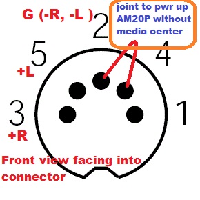 Problem: AM20P now is giving a intermittent power problem. unit will not turn on when switch on .. need to switch on & off a few time if lucky, then it will functions as normal until i shut it off. attach a pic for your reference. 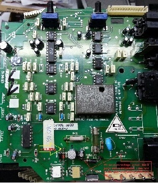 1. upon checking the +12v at the 2 Diode as per highlighted in the picture, i get +11.67v 2. Replace 2 optocoupler U401 _4N32 & U402_TLP3063 yield same results 3. Replace LM339N yield same results 4. R412 measure 380ohm & R437 is around 7.5kohm 5. As highlighted in pic, if i measure the voltage across last pin of opto U402 to ground( cathode of diode ), i can turn on the amp and it will function as normal. my last suspect is the 2 opamp 4559D ( U101 & U 301) near the audio input area. i am a bit loss & Hope you can kindly point me to the right directions. many thanks in advance. regards kt |
|
New member Username: VbublePost Number: 1 Registered: Dec-15 | Dear all BOSE expert I have Lyfestyle 12 sys. and my music center is mechanicaly destroyed. I am planing to activate acoustimass amplifier with speakers by use of some tuner. Pls let me know how to activate amplifier on 8 pin DIN connector, by adding voltage or by shorting some control pins in the 8 pin DIN connector. Thanks. Greatings from sunny CROATIA |
|
New member Username: Liza44Post Number: 1 Registered: Jun-16 | I had my box made for 2 jlW7s by Fatbox USA. They did a great job and my SPL went way up. I drive a Tahoe, now that I have a ported box the dash actually jumps up and down lol. I dynamited my truck with the NVX sound dampener and it worked awesome! I'm putting realistically 900watts to ea W7 and they love it! If the subs were cheaper I'd build a wall for 6 of these pigs and do second skin application. Be advised you will need a powerful 4ch amp to drive your surround speakers. I have 2 sets of JLC5-650 components and 2 sets of Focal PC690 6x9s to keep up when the bass is cranking. These are great OVERALL subs, if you want big sloppy sounding SPL go buy Kickers,Sundown,DC audio,earthquake ect. If you want pure clean bass you can tweak to your taste, go buy a W7 and get a custom vented box. 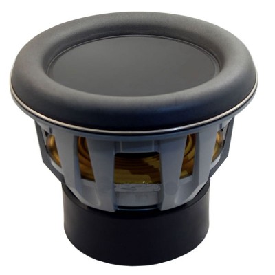 |
|
New member Username: VondesPost Number: 8 Registered: Aug-17 | am using Bose Life Style 20. The CD magazine is stuck and making noise. Could you please send me the instruction on how to fix this problem? |
|
New member Username: JfalmeidaPorto, Grande Porto Portugal Post Number: 1 Registered: Feb-23 | Does anyone have the service manual of lifestyle 5 or 12? I want to ensure I find R428. The service manual I've found doesn't seems to have the schematics. Thanks |
Main Forums
Today's Posts- Home Audio Forum
- A/V Receivers Forum
- Amps Forum
- Cassette Forum
- CD Players Forum
- CD Recorders Forum
- DAC & Transports Forum
- DVD-Audio & SACD Forum
- Equalizers Forum
- Integrated Amps Forum
- iPod Docks Forum
- MiniDisc Forum
- Mini Systems Forum
- Digital Music Systems Forum
- Phono Forum
- Preamps Forum
- Speakers Forum
- Subwoofers Forum
- Tuners Forum
- Home Video Forum
- Home Theater Forum
- Car Audio Forum
- Accessories Forum
- All Forum Topics